 9/5/06
I ordered kit 13 this morning.
9/5/06
I ordered kit 13 this morning.
9/5/06
I ordered kit 13 this morning.
10/5/06 Kit 13 arrived at 7.30 this morning. It consists of the valve motion - return cranks, eccentric rods, expansion links, radius rods, lifting links, combination levers and links, valve crossheads, weighshaft and reversing screw - along with the lubricator assemblies. All the parts seem present and correct, although I know that the return cranks and eccentric rods are due to be replaced because of the problem I described in kit 12 on 7/5/06. Some of the rods are blackened, presumably because they have been case-hardened - hopefully this will polish off. The numbering of some of the bags of lubricator parts differs from that in the parts list, but I think that they are all there. The ISO drawing of the lubricator is missing, so I'll ask Debbie for this. The instructions say that the lubricators cannot be fitted until the next kit - it looks as though different spacer plates are needed here. We're going to be away sailing for the next few days, so there'll probably be no more updates until Sunday.
 14/5/06
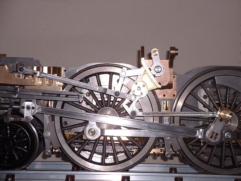
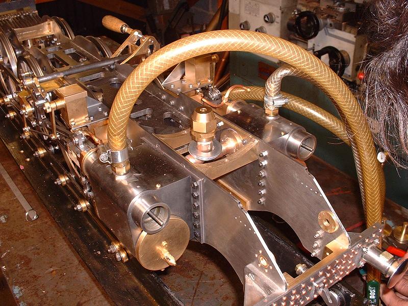
Back from a very pleasant three days sailing in the Solent, visiting Cowes and Portsmouth. This morning I went to the St Albans MES track near Kings Langley and drove half a dozen circuits on the club loco, a modified Simplex tank engine. I started to get the hang of using the cut-off lever as well as the regulator to conserve steam, and adjusting the axle pump bypass to keep the boiler water level correct. Unfortunately I didn't put enough coal on the fire, so ran out of steam half way round the track and suffered the ignominy of being pushed back to the station by a diesel shunter! This afternoon I've done a trial assembly of the left-hand valve motion and the weighshaft. This went together easily enough, with just a little filing of the expansion link slot to get a good sliding fit for the brass die block. This photograph shows the result, and demonstrates the problem with the geometry - at this point the top rear corner of the expansion link is just hitting the weighshaft arm boss, but the return crank is still a long way from reaching its front dead centre. Also with the reversing gear little more than halfway down into the forward (lower) sector of the expansion link, the valve crosshead has reached the front of its slides. I don't think this latter point will necessarily be a problem once the expansion link travel has been sorted out, since the lower end of the combination lever, attached to the piston crosshead, should be halfway back by the time the radius rod is fully forward. It does however demonstrate that the problem is the excessive travel of the expansion link rather than just an obstruction on the weighshaft - the current geometry would not work even if the weighshaft boss didn't get in the way. Debbie has confirmed that the return cranks and eccentric rods will be replaced.
14/5/06
Back from a very pleasant three days sailing in the Solent, visiting Cowes and Portsmouth. This morning I went to the St Albans MES track near Kings Langley and drove half a dozen circuits on the club loco, a modified Simplex tank engine. I started to get the hang of using the cut-off lever as well as the regulator to conserve steam, and adjusting the axle pump bypass to keep the boiler water level correct. Unfortunately I didn't put enough coal on the fire, so ran out of steam half way round the track and suffered the ignominy of being pushed back to the station by a diesel shunter! This afternoon I've done a trial assembly of the left-hand valve motion and the weighshaft. This went together easily enough, with just a little filing of the expansion link slot to get a good sliding fit for the brass die block. This photograph shows the result, and demonstrates the problem with the geometry - at this point the top rear corner of the expansion link is just hitting the weighshaft arm boss, but the return crank is still a long way from reaching its front dead centre. Also with the reversing gear little more than halfway down into the forward (lower) sector of the expansion link, the valve crosshead has reached the front of its slides. I don't think this latter point will necessarily be a problem once the expansion link travel has been sorted out, since the lower end of the combination lever, attached to the piston crosshead, should be halfway back by the time the radius rod is fully forward. It does however demonstrate that the problem is the excessive travel of the expansion link rather than just an obstruction on the weighshaft - the current geometry would not work even if the weighshaft boss didn't get in the way. Debbie has confirmed that the return cranks and eccentric rods will be replaced.
15/5/06 I started to clean up and fit the left-hand valve motion. The black surface colouring of the case-hardened parts polishes off quite easily with emery cloth. Both combination levers turned out to be slightly bent in an identical manner - perhaps as a result of the quenching after the case-hardening? I straightened one of them and fitted the combination lever, combination link and the valve crosshead. The brass sliding blocks needed filing slightly to fit between the slide bars. The top of the inner rear boss on the combination link needed filing slightly to clear the bottom of the crosshead. The locknut supplied for the valve spindle was 4BA and should be M4, but I had some spares. The ISO drawings in the instruction pack show the combination lever fitted back to front - the oiler on the lower bearing should be towards the rear, as shown here.
17/5/06 I've continued with the left-hand valve motion, polishing and fitting the motion bracket and its bushes, the expansion link, and the radius rod. I'm planning to fit the pivot pins with their split pins on the inside, because I think they look rather untidy on the outside - there seems to be plenty of room to do this except possibly on the pin connecting the expansion link to the eccentric rod, where the inner end is quite close to the connecting rod.
 18/5/06
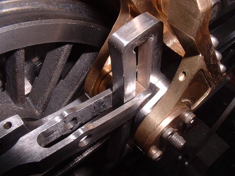
I fitted the expansion link pivot blocks and fitted the end of the radius rod over the pins of the die block in the expansion link slot. This proved slightly tricky because the arms of the radius rod have to be prised apart quite a way to fit over the die block, and they then don't spring back completely to give a close fit around the expansion link. The result is that the radius rod tends to catch on the expansion link pivot blocks as it passes through the neutral position. I eventually solved this by clamping the ends of the radius rod tightly against the expansion link, and then prising the arms apart near the lifting arm pivot hole to restore some inward pressure at the ends. The photograph shows the result. The three M2.5x8 socket head screws at the upper right of the picture holding the outer brass plate to the main motion bracket seem rather short for the job, since the bracket is over 5mm thick and so less than 3mm of thread is engaged. I've asked Debbie for some longer ones. Incidentally the blemishes and dust particles in the photo are completely invisible to the naked eye - the macro zoom and flash on the camera are very unforgiving.
18/5/06
I fitted the expansion link pivot blocks and fitted the end of the radius rod over the pins of the die block in the expansion link slot. This proved slightly tricky because the arms of the radius rod have to be prised apart quite a way to fit over the die block, and they then don't spring back completely to give a close fit around the expansion link. The result is that the radius rod tends to catch on the expansion link pivot blocks as it passes through the neutral position. I eventually solved this by clamping the ends of the radius rod tightly against the expansion link, and then prising the arms apart near the lifting arm pivot hole to restore some inward pressure at the ends. The photograph shows the result. The three M2.5x8 socket head screws at the upper right of the picture holding the outer brass plate to the main motion bracket seem rather short for the job, since the bracket is over 5mm thick and so less than 3mm of thread is engaged. I've asked Debbie for some longer ones. Incidentally the blemishes and dust particles in the photo are completely invisible to the naked eye - the macro zoom and flash on the camera are very unforgiving.
20/5/06 Debbie sent me some M2.5x12 screws for the motion plate, which look much more secure. I've now fitted the right-hand motion bracket and the combination lever, combination link and valve crosshead. When the combination levers are rocked fully forward they hit the top front inner edge of the valve rod clevis, so I filed the latter to give more clearance. I also checked the left-hand valve setting. With the radius rod in neutral and the connecting rod at the mid-point of its travel, the valve crosshead is close to the mid-point of its slides, and this looks OK. However, the valve bobbin should then be at the mid-point of the cylinder, and to achieve this I needed to move it back as far as it would go - screwing the valve rod right into the crosshead, and fixing the bobbin right at the rear end of the threaded section with only one nut behind it. Ted had forewarned me about this - it looks as though the thread on the valve rod will need to be extended back by 5mm or so in order to leave room for adjustment. I'll ask Debbie about this - there have been no instructions yet on setting the valve timing. I believe that the fine adjustment of the valves is done by slackening the locknut on the crosshead and screwing the rod in or out of the clevis, taking the front cover off the valve cylinder to turn the rod. George recommended filing flats on the front end of the rod to make it easier to adjust.
22/5/06 I polished and fitted the right-hand expansion link and radius rod. I noticed that no oil holes had been drilled for the bearings on the expansion links that connect to the eccentric arms, so I drilled these out - 2.7mm for the oil reservoir and 1.2mm for the hole through the bush. The outer bearings for the expansion link pivots are fixed to the motion brackets with four screws, and strangely these are different sizes on the two sides - the kit provides M2.5 socket head screws for the left and M2 for the right, but in fact the right-hand threads are 6BA. I substituted hex head bolts on both sides, since these look more realistic than socket heads (although the real locomotive has rivets here). I had some M2.5 bolts spare from the rear lifting lugs on the tender, where I had used rivets in place of the bolts provided. The photo taken on 18/5 above shows the original socket heads. M2.5x12 bolts would also look more realistic for attaching the motion plate, but I daren't ask Debbie for these having just got the longer socket head screws!
 23/5/06
I polished and fitted the weighshaft, lifting cranks and reversing screw. The lifting cranks come already silver-soldered to their bosses, and each boss is fixed to the weighshaft with a roll pin (a spring steel tube with a longitudinal slot driven into a hole through the boss and weighshaft). I haven't inserted the second roll pin yet, because it might be difficult to remove when I come to dismantle for painting. Everything worked smoothly after a little filing and realignment of the forks into which the reversing nut fits. I had to run an 8mm drill through the holes in the motion bracket to get the front reversing screw bearing to fit - the hole was decidedly elliptical. The reversing screw is inserted from the rear into its front and rear bearings in the motion bracket, and there is nothing to stop it sliding backwards. The weight of the radius rods tends to pull it forwards when stationary, but there is an upwards force on the radius rods for half of each valve stroke caused by the angle of the expansion link slot. There will presumably be a universal joint and a rod leading back to the reversing gear in the cab in a later kit, but it seems unwise to rely on compression in this long linkage to hold the screw in place. I noticed that the Modelworks control model on show last Sunday had a small screw and washer threaded into a hole drilled in the front of the reversing screw, presumably to solve this problem. I'll check with Debbie whether this is the permanent solution and whether a new reversing screw is going to be provided.
23/5/06
I polished and fitted the weighshaft, lifting cranks and reversing screw. The lifting cranks come already silver-soldered to their bosses, and each boss is fixed to the weighshaft with a roll pin (a spring steel tube with a longitudinal slot driven into a hole through the boss and weighshaft). I haven't inserted the second roll pin yet, because it might be difficult to remove when I come to dismantle for painting. Everything worked smoothly after a little filing and realignment of the forks into which the reversing nut fits. I had to run an 8mm drill through the holes in the motion bracket to get the front reversing screw bearing to fit - the hole was decidedly elliptical. The reversing screw is inserted from the rear into its front and rear bearings in the motion bracket, and there is nothing to stop it sliding backwards. The weight of the radius rods tends to pull it forwards when stationary, but there is an upwards force on the radius rods for half of each valve stroke caused by the angle of the expansion link slot. There will presumably be a universal joint and a rod leading back to the reversing gear in the cab in a later kit, but it seems unwise to rely on compression in this long linkage to hold the screw in place. I noticed that the Modelworks control model on show last Sunday had a small screw and washer threaded into a hole drilled in the front of the reversing screw, presumably to solve this problem. I'll check with Debbie whether this is the permanent solution and whether a new reversing screw is going to be provided.
 24/5/06
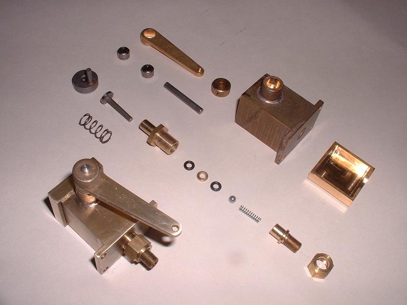
I assembled one of the lubricators - the ISO drawing referenced in the instructions doesn't seem to exist, but it went together easily enough without the help of this. The one-way clutches are very neat - they look like small ball races, 8mm outside diameter and 4mm inside, and they grip the shaft in one direction only. One fits into the boss on the lubricator body, and the other into the boss of the operating lever, arranged so that the one in the lever grips in one direction and the one in the body stops the shaft turning in the other direction on the return stroke. I arranged them so that the working stroke is pulling towards the rear, so that the wire rod connecting to the lever on the end of the expansion link pivot is in tension rather than compression. A cam on the shaft inside the lubricator body operates the piston rod, which pushes down through the pump body, through two O-rings and against a spring-loaded ball. This spring needed shortening by 2mm, as predicted in the instructions. The two clutches were a very tight fit in their bosses - I thought when they were half way in they were going to jam solid, but I held my breath and used the vice and they went in with no apparent damage. A slender half-inch AF socket or tube spanner is needed to screw the pump body into the lubricator body from above. The assembled lubricator works very nicely. The shaft could be shortened slightly for cosmetic reasons, as could the grub screw in the knurled wheel used for manual pumping - I haven't done this yet. The photo shows the assembled lubricator along with the parts for the other one.
24/5/06
I assembled one of the lubricators - the ISO drawing referenced in the instructions doesn't seem to exist, but it went together easily enough without the help of this. The one-way clutches are very neat - they look like small ball races, 8mm outside diameter and 4mm inside, and they grip the shaft in one direction only. One fits into the boss on the lubricator body, and the other into the boss of the operating lever, arranged so that the one in the lever grips in one direction and the one in the body stops the shaft turning in the other direction on the return stroke. I arranged them so that the working stroke is pulling towards the rear, so that the wire rod connecting to the lever on the end of the expansion link pivot is in tension rather than compression. A cam on the shaft inside the lubricator body operates the piston rod, which pushes down through the pump body, through two O-rings and against a spring-loaded ball. This spring needed shortening by 2mm, as predicted in the instructions. The two clutches were a very tight fit in their bosses - I thought when they were half way in they were going to jam solid, but I held my breath and used the vice and they went in with no apparent damage. A slender half-inch AF socket or tube spanner is needed to screw the pump body into the lubricator body from above. The assembled lubricator works very nicely. The shaft could be shortened slightly for cosmetic reasons, as could the grub screw in the knurled wheel used for manual pumping - I haven't done this yet. The photo shows the assembled lubricator along with the parts for the other one.
25/5/06 I assembled the second lubricator. Debbie responded on the question I raised on 23/5 about the reverser screw, saying that she would look into it further but that she personally favoured putting a retaining screw into the front of the reverser screw as on the control model. I also checked with George, who has the earlier Winson version of the Britannia - he says that the arrangement is the same, and he has not had problems with it. Perhaps when the valve pistons have been run in and the motion is less stiff, there is less tendency for the radius rods to lift. I'll leave it as it is for the time being. Debbie also told me that she is sending out sets of cylinder cocks today, but these have not been drilled and they will be replaced later (unless people want to drill them themselves). However, I guess they will be useful for testing on air, and they will also prevent the oil that I put into the cylinders from dribbling out of the empty holes.
26/5/06 I've now completed kit 13, apart from fitting the modified return cranks and eccentric rods when they arrive. I'll order kit 14, the smokebox, next week. In the meantime I'll probably do a bit more painting. Tomorrow I'm going to the GCR at Loughborough to do a day's volunteer work on the restoration of the full-size Oliver Cromwell.
15/7/06 I've now received my replacement driving wheels, return cranks and eccentric rods. The eccentric rods are about 3mm shorter than the originals, and the return cranks have the four screw holes drilled at an angle to the line of the crank to reduce the throw, and the screw holes are slightly smaller to give a more precise registration. A very quick trial assembly of the left-hand motion suggests that the problem has been solved - the motion makes a full revolution in full forward gear without anything fouling, and the valve crosshead moves over exactly the full length of its guides.
16/7/06 I checked the new driving wheels, which look good, and I polished and fitted the left-hand return crank and eccentric rod. I then checked the motion more carefully. Although as I said yesterday the motion looks spot-on in full forward gear, the valve crosshead was slightly too far forward, just by 1 or 2mm, in neutral and reverse gear. I came to the conclusion that the motion bracket supporting the weighshaft and expansion link pivot was too far forward by the same amount - this makes no difference in full forward gear, when the radius rod is more or less in line with the eccentric rod, but it accounts for the difference in neutral and reverse when the radius rod is raised. The weighshaft was also slightly forward of the centre of the semicircular indentation in the top of the frames designed to accommodate it, reinforcing the conclusion. I therefore removed the motion bracket and eased the holes in the frame backwards by 1mm or so with a round file. This did improve the motion in neutral and reverse - it's not perfect, but I guess that the motion in forward gear is the key thing. Another minor issue was that the top front corner of the expansion link hit the boss of the lifting link when the latter was in line with it, at about 25% forward gear. I fixed this by filing the boss more or less flat - it's not visible between the lifting cranks. I'll probably also round off the front and rear top corners of the expansion link a little, to make quite sure that they don't hit anything.
17/7/06 Having improved the motion by moving the motion bracket backwards 1mm, I decided to go the whole hog and move it a further 1mm back - this makes the valve crosshead movement pretty accurate in forward, neutral and reverse. Having elongated the fixing holes in the frame so much, I'll probably drill and fit a couple of additional locating pins when I'm sure of the final position. I also removed 1mm or so from the top corners of the expansion link by increasing the radius of the corners. My only remaining observation on the motion is that the radius rod does not move quite to the ends of the expansion link slot to get full valve travel, which suggests that the throw of the return crank may be still slightly too large. I don't think that this is a problem - it's certainly better than not getting enough valve movement - but I'll probably need to add a couple of collars to the ends of the reversing screw to prevent the radius rod being moved too far and causing the valve crosshead to hit the ends of its slide, which could cause serious damage to the motion. I also completed the top tender steps today - see photo under kit 4.
23/7/06 I continued fitting the balance plates to the new driving wheels. Ted tells me that he has run successfully on compressed air for the first time, which is excellent news.
26/7/06 I've finished cleaning up the new driving wheels and fitting their balance plates, and I've fitted the new return crank and eccentric rod on the right-hand side. I had to deepen the counterbores in the return crank bolt holes with a 4mm drill in order to get the socket head screws almost flush with the cranks and avoid them fouling the eccentric rods. I now just need to make the same adjustments to the valve gear as on the left-hand side to get the correct valve motion in neutral and reverse. I discovered that the right-hand connecting rod was very slightly bent, which caused it to bind - the little end was a couple of mm out from the slot in the crosshead. When I turned it over it was too far in by the same distance, which proved that it was the rod itself that was the problem. I straightened it by supporting the ends and pulling the middle down hard with a clamp, which cured the problem. Goodness knows how it got bent, because it took considerable force to straighten it. The whole chassis rolls reasonably easily now - it's obviously still a bit stiff, but it feels uniform across a full revolution of the wheels.
27/7/06 I adjusted the position of the right-hand motion bracket to get a reasonable valve motion at the valve crosshead. I then roughly set the valve timing for each cylinder by blowing into its steam pipe while rolling the locomotive backwards and forwards and checking when the air pressure reached the front and rear cylinder cock holes. I screwed the valve piston in and out of its crosshead until I got roughly equal timing on the front and rear of the piston. I noticed that there seemed to be a slight leakage to exhaust around the right hand valve piston at all positions. I swapped the complete valve piston assemblies over and the leak remained on the right hand cylinder. I've arranged to take my model to Modelworks on 16th August to test it on air, and Debbie says that she will look into the problem then. I now just need to dismantle the wheels and axles in order to glue the axles and crankpins.
15/8/06 Having glued the wheels, I reassembled all the motion gear complete with split pins and reset the valve timing in preparation for my visit to Modelworks tomorrow. The chassis rolls reasonably freely - it takes a force of about 2-3Kg weight to move it along the track.
 16/8/06
Just back from an interesting day at Modelworks with Debbie and Ian, testing on compressed air. Ted came along to watch the proceedings - he has already briefly tested his model on air at home, but Debbie said that I was the first builder to bring a Britannia in for testing. We placed the chassis on the rolling road and connected the compressed air lines to the cylinders, with a separate valve on each hose. We oiled up, placed the valve gear in full forward and turned on the air, and it sprang to life immediately and ran very vigorously, so my valve settings must have been pretty much correct. Ian then adjusted the valves - he removed the front covers, then ran the model with air pressure on just one cylinder at a time, screwing the valve piston rod in and out of the valve crosshead while the engine was running and listening to the change in the beat. He filed a square end onto the front of each valve piston rod and attached a small pin vice to assist in adjusting it. I was pleasantly surprised that the engine would run quite happily on just one cylinder. We then tried reducing the air pressure and also reducing the cut-off on the reversing gear, and the engine continued to run happily. It became noticeably freer after about ten minutes running, and would run on air pressure down to about 20psi, which was very satisfactory. We then tried reverse gear and it ran, but the timing was a bit out - as I explained on 17/7/06 above, I had improved the valve motion by moving the motion brackets backwards by a couple of mm, but it was still not completely right.
Ian agreed that it should be sorted out properly, and he proceeded to make a shorter radius rod by cutting a spare one and welding the two halves together, making it about 1.5mm shorter. This helped the balance between forward and reverse, but meant that the eccentric rod needed lengthening to compensate. Ian also agreed that the throw of the return crank should be reduced further to allow the full length of the expansion link to be used, as I mentioned on 17/7/06 above. Ian and Debbie promised to talk to the designer and test out these further improvements on the control model, and produce new parts in due course. I felt very happy with this outcome - I now know that the model already works well, and should be spot on with these further modifications. I also pointed out the leak to exhaust that I mentioned on 27/7/06 above - this affected both cylinders at the higher pressure of this test. Ian felt that it was probably leakage past the valve piston rings that would improve with running in, but I'll clearly need to watch this when I test on steam. It could also be leakage between the front and rear halves of the valve liners and the cylinder block - the liners are pressed in from each end.
16/8/06
Just back from an interesting day at Modelworks with Debbie and Ian, testing on compressed air. Ted came along to watch the proceedings - he has already briefly tested his model on air at home, but Debbie said that I was the first builder to bring a Britannia in for testing. We placed the chassis on the rolling road and connected the compressed air lines to the cylinders, with a separate valve on each hose. We oiled up, placed the valve gear in full forward and turned on the air, and it sprang to life immediately and ran very vigorously, so my valve settings must have been pretty much correct. Ian then adjusted the valves - he removed the front covers, then ran the model with air pressure on just one cylinder at a time, screwing the valve piston rod in and out of the valve crosshead while the engine was running and listening to the change in the beat. He filed a square end onto the front of each valve piston rod and attached a small pin vice to assist in adjusting it. I was pleasantly surprised that the engine would run quite happily on just one cylinder. We then tried reducing the air pressure and also reducing the cut-off on the reversing gear, and the engine continued to run happily. It became noticeably freer after about ten minutes running, and would run on air pressure down to about 20psi, which was very satisfactory. We then tried reverse gear and it ran, but the timing was a bit out - as I explained on 17/7/06 above, I had improved the valve motion by moving the motion brackets backwards by a couple of mm, but it was still not completely right.
Ian agreed that it should be sorted out properly, and he proceeded to make a shorter radius rod by cutting a spare one and welding the two halves together, making it about 1.5mm shorter. This helped the balance between forward and reverse, but meant that the eccentric rod needed lengthening to compensate. Ian also agreed that the throw of the return crank should be reduced further to allow the full length of the expansion link to be used, as I mentioned on 17/7/06 above. Ian and Debbie promised to talk to the designer and test out these further improvements on the control model, and produce new parts in due course. I felt very happy with this outcome - I now know that the model already works well, and should be spot on with these further modifications. I also pointed out the leak to exhaust that I mentioned on 27/7/06 above - this affected both cylinders at the higher pressure of this test. Ian felt that it was probably leakage past the valve piston rings that would improve with running in, but I'll clearly need to watch this when I test on steam. It could also be leakage between the front and rear halves of the valve liners and the cylinder block - the liners are pressed in from each end.
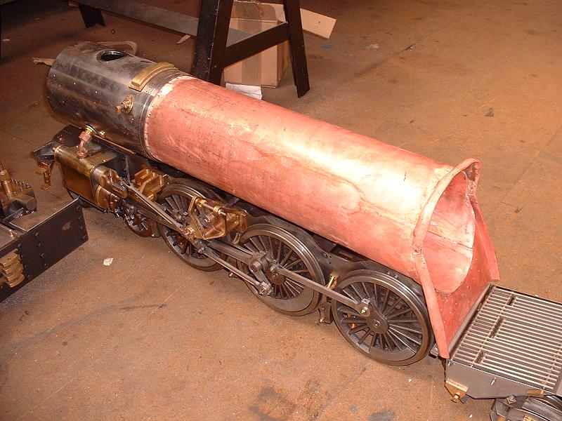
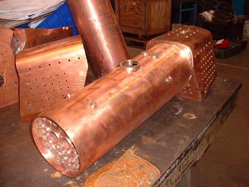 We also saw the prototype boiler in the factory, and I was very impressed with the quality of the workmanship as shown in this photograph. The boiler has a tapered barrel and the prototype has a reinforcing strip brazed over the outside of the joint along the bottom of the boiler. The new boiler regulations require this to be on the outside rather than the inside, presumably so that the inspector can see that it's there. This strip fouls the weighshaft and the rear stretcher on the prototype, so the joint is being placed to one side on the production boilers to avoid this problem. The second photograph shows the barrel of one of these boilers on the control model, and it appears to fit very nicely - the joint can just be seen on the lower right-hand side.
9/11/06 I visited Modelworks today to collect my boiler, and Debbie gave me some news about the modifications to the valve gear discussed above. New radius rods, eccentric rods, crankpins and reverse cranks will be supplied in a few weeks' time, so if you haven't already glued your crankpins to the driving wheels, don't!
7/5/07 It's now six months since I wrote the last entry above, and there's still no sign of the revised valve gear. Debbie has assured me that new shorter radius rods will be produced, but has no information on the other parts. Since I have some spare return cranks (I was sent a set with the first modification on 15/7/06 and then again in kit 16), I plan to drill a hole through the centre of a spare return crank and into the centre of the crankpin, so that I can clamp it with a countersunk screw and adjust the throw. I should then be able to work out exactly what throw is needed for full travel in the expansion link, and also measure up exactly what length the radius rods and eccentric rods need to be. Although I'm not an expert in Walschaerts' valve gear, it seems to me that the set-up procedure should be as follows:
8/5/07 I've now fitted a temporary return crank to the left-hand side as described above, using an M3 countersunk allen screw into the centre of the crankpin, and set it to give full valve travel with the die block at the bottom of the expansion link slot. I then measured the travel of the valve crosshead in forward, neutral and reverse - the figures are the gap in front of the valve crosshead when fully forward, and behind it when fully back. I started with the weighshaft brackets moved back about 2mm as described on 16-17/7/06 above:
I then measured the movement with the weighshaft in its standard position:
So, if Modelworks produce new radius rods about 2mm shorter, I'll use those with the weighshaft in the standard position and the original eccentric rods, and I think that will be pretty accurate. If they don't, I'll move the weighshaft back and make eccentric bushes for the new eccentric rods to lengthen them by 0.8mm, and that should be spot on. If they don't produce new return cranks, I'll probably redrill the crankpins as described yesterday. Incidentally please don't rely on my measurements for your own build - I suspect that there is sufficient free play in the bolt holes for the cylinders and weighshaft brackets to make for slight differences between builds.
14/5/07 I didn't visit the Harrogate show this year, but Richard tells me that he spoke to Ian on the Modelworks stand and was told that the valve gear modifications will be done but it will take at least 8 weeks. I'm not sure why it has to take so long - I would have thought that an hour or two measuring up followed by a quick run on the CNC machines would solve the problem. I've measured the throw diameter of the various return cranks as follows:
16/5/07 I removed the valve piston from the right-hand cylinder and inspected the bore with a strong light. It seemed to be polished in some areas and matt grey in others, suggesting that the leakage might be past the valve piston rings after all. I posed the problem on the Model Engineering Clearing House in this thread. Following advice from 'Baggo', I applied lots of thick steam oil to the liner and found that this improved the seal and also that the leakage then varied according to the position of the valve, proving that at least some of the leakage is around the valve piston rings. In view of this I've decided to wait until I can test on steam and see if the leakage is reduced with more running in. I don't intend to paint the locomotive until I have steamed successfully, so I will still be able to ask Modelworks to replace the cylinder at that stage if necessary.
4/7/07 I had a call from Arthur Coleman today - he's one of the design team at Modelworks and he phoned to assure me that he is sorting out the valve gear, including the return cranks, as part of the final kit delivery. We discussed the issues and I'll report back when Arthur has finalised the changes.
 16/9/07
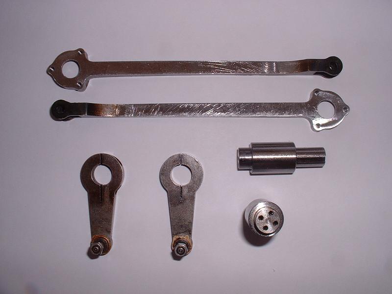
The replacement valve gear parts supplied in kit 18b consist of new crankpins, return cranks and eccentric rods, as shown in this photograph. There are no new radius rods, and the new eccentric rods turn out to be identical to the original ones, prior to the first set of replacements! The return cranks are adjustable and clamp around the new crankpins which have longer and thinner extensions. The crankpins have 4 holes for cosmetic bolts, so they look reasonably realistic although obviously not quite as accurate as the original non-adjustable design. For those of you who followed my advice on 9/11/06 above and didn't glue your crankpins, I think the new return cranks are a good solution. However, I'm very reluctant to change my crankpins at this stage since the heat needed to release the Loctite would risk weakening the axle joints as well and to be safe I'd have to remake these, potentially disturbing the wheel quartering. I shall press Modelworks to make new return cranks to the original design but with a smaller fixed throw, which is what I suggested to Arthur some time ago. I'd already heard that Modelworks didn't think that new shorter radius rods were needed, which Ted and I both found baffling, but then I remembered that the control model had been assembled with its combination levers back to front - the oilers on the bottom bearing should face to the rear, as I pointed out on 15/5/06 above. This shouldn't have changed the geometry - the Spink drawings show the 3 holes in the combination levers in a straight line - but in fact I discovered that they are about 0.5mm out of line, making an effective difference of 1mm in the required length of the radius rods, which explains at least half of the discrepancy. Modelworks have now turned round their combination levers and I think accept that shorter radius rods are needed - they are sending Ted a set to try out on his model and on mine, and will produce a batch when we have checked them.
16/9/07
The replacement valve gear parts supplied in kit 18b consist of new crankpins, return cranks and eccentric rods, as shown in this photograph. There are no new radius rods, and the new eccentric rods turn out to be identical to the original ones, prior to the first set of replacements! The return cranks are adjustable and clamp around the new crankpins which have longer and thinner extensions. The crankpins have 4 holes for cosmetic bolts, so they look reasonably realistic although obviously not quite as accurate as the original non-adjustable design. For those of you who followed my advice on 9/11/06 above and didn't glue your crankpins, I think the new return cranks are a good solution. However, I'm very reluctant to change my crankpins at this stage since the heat needed to release the Loctite would risk weakening the axle joints as well and to be safe I'd have to remake these, potentially disturbing the wheel quartering. I shall press Modelworks to make new return cranks to the original design but with a smaller fixed throw, which is what I suggested to Arthur some time ago. I'd already heard that Modelworks didn't think that new shorter radius rods were needed, which Ted and I both found baffling, but then I remembered that the control model had been assembled with its combination levers back to front - the oilers on the bottom bearing should face to the rear, as I pointed out on 15/5/06 above. This shouldn't have changed the geometry - the Spink drawings show the 3 holes in the combination levers in a straight line - but in fact I discovered that they are about 0.5mm out of line, making an effective difference of 1mm in the required length of the radius rods, which explains at least half of the discrepancy. Modelworks have now turned round their combination levers and I think accept that shorter radius rods are needed - they are sending Ted a set to try out on his model and on mine, and will produce a batch when we have checked them.
25/3/08 Another six months have passed since my last entry on this topic, and there's no sign of Modelworks doing anything more to sort out the valve gear. I'm keen to be ready to steam when the final parts for kit 18b arrive, so I've decided to finalise the valve gear with the parts that I've got. I'll start by positioning the weighshaft brackets to get balanced movement in forward and reverse. I'll then decide what to do about the return cranks. Interestingly Doug Hewson contacted me a few weeks ago to say that on the Winson Britannias he had to move the left hand weighshaft bracket forward a few mm to get the motion correct, and everything was then spot on. On this Modelworks version it looks as though we need to move both brackets back.
27/3/08 Doug Hewson tells me that full valve travel on the Winson version is 7/16", ie 11.1mm. If this is the same on the Modelworks version - and I'd be grateful if anyone with a copy of the Spink plans could confirm the valve travel shown there - it means that there is sufficient leeway within the 16.7mm maximum possible movement in the valve guides for the centring to be only a cosmetic issue. The valve crosshead could be as much as 2.5mm forward of the centre of the guides and still give full valve travel. I've set up the left hand valve gear with the weighshaft bracket in pretty much the standard position and with the original (longer) eccentric rods, and this gives balanced movement in forward, mid-gear and reverse, but in each case with the valve crosshead about 2.5mm forward of the centre. There's still the option of moving the brackets back 3mm and using the shorter eccentric rods, which would look more central, and I may yet decide to do this (particularly since I've already filed and polished the shorter rods!). Once the movement is the same in forward and reverse, it's just a matter of fine-tuning the position of the valve bobbin on its spindle to give an even beat in forward gear.
29/3/08 Turning to the return cranks, I've got a bit of a confession to make. I'd previously concentrated on setting them so that the radius rods could be lowered right to the bottom of their expansion link slots for full forward gear, which requires quite a short throw on the return cranks - see 7/5/07 above. I've since come to realise that the more important thing is to get the valve timing right, which requires the eccentric rod motion to be 90 degrees out of phase with the connecting rod motion. This means that the return crank angle must be set so that its crankpin trails the main crankpin by just over 90 degrees. The extra few degrees are caused by the fact that a line through the front eccentric rod pivot and the driving axle is inclined very slightly further above the horizontal than a line through the front pivot of the connecting rod and the driving axle. Modelworks did give instructions in kit 18b with the new adjustable return cranks that achieve this valve timing, by adjusting the return crank angle so that the distance from the return crank pin to the expansion link bearing (with the expansion link fixed vertically) is the same when the piston is on front dead centre as it is when on back dead centre. I've set my home-made adjustable return crank to achieve this (I found it easier to fit the eccentric rod and then measure the distance from its front pivot to a fixed point on the slides when at front and back dead centres), and, embarrassingly, it turns out that the correct angle is achieved when the throw of the return crank is about 31mm, ie almost exactly the throw of the second set of fixed return cranks (see 14/5/07 above). In view of this, I'll probably use these fixed return cranks, which look nicer than the adjustable ones. My apologies to Modelworks and to anyone who has been misled by my earlier comments! Of course, this still doesn't explain why we can't use the full length of the expansion link slot - this would require a shorter return crank set at a smaller angle in order to give a shorter throw with the correct timing. All three return crank versions supplied by Modelworks are the same length and are only about 0.7mm longer than the 1.401" shown on the Spink plans. Paul T has kindly offered to lend me his Spink plans and the Martin Evans book on valve gears, so I'll peruse these to try and find where the differences arise, and to check that I haven't made any other incorrect assumptions.
31/3/08 The plans and book arrived this morning - thanks, Paul! An initial check reveals the following:
5/4/08 I've now finally set up the valve gear to my satisfaction. I moved both weighshaft brackets back by about 2.5mm to centralise the valve crosshead motion when in neutral gear. I then used the shorter eccentric rods and made new off-centre bearings in the expansion links to increase the effective length of the eccentric rods by nearly 1mm, and this gives balanced movement in both forward and reverse (I made the off-centre bearings from the spare spacers for the middle regulator bracket in kit 18b, filing out the 3mm holes to be eccentric and then running a 5mm drill through). I used the second set of fixed return cranks, which give a throw of 31mm and the correct valve timing, and I filed a bit more off the top corners of the expansion links to avoid them touching the weighshaft bosses. I'd previously filed the upper bosses on the lifting links to stop the expansion links touching them in half-forward gear. I set the valve bobbins by subtracting the length of the bobbin from the overall length of the valve liners and halving this to give the depth of the front of the bobbin from the front of the liner when centralised in the liners - I calculated this depth as 36.8mm. I then measured the depth of the bobbin at the front and back of its travel in full forward gear, using the depth gauge on my digital calipers, and took the mean of these to give the position of the front of the bobbin at its mid travel. I then screwed the valve spindle in or out of its clevis to achieve the required 36.8mm. I'll now drill some extra holes through the weighshaft brackets and frames to register them permanently. I'll also fit locknuts to the reversing screw to limit the lifting arm travel to that needed for full valve travel, which occurs at about 75% of the way down the expansion link slot.
 9/4/08
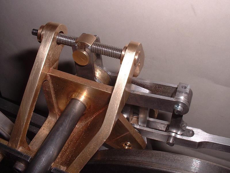
I've fixed the weighshaft brackets to the frames using M4 bolts with the nuts on the outside, which are much easier to do up than the allen screws supplied - it's almost impossible to get at the allen screws under the stretcher without turning the frames upside down, which I can no longer do. I've fitted two half-nuts to each end of the reversing screw, which limits the travel by the right amount. I've also fitted the dummy restoring spring cylinder to the right-hand weighshaft bracket as shown in the photo - I made a steel bracket and soldered it into a slot in the cylinder. Modelworks have not described how to fit this part, and have not provided a bracket. The screw holes in the rear end suggest that they intended to mount it under the running board, but I think that my method is closer to the prototype.
9/4/08
I've fixed the weighshaft brackets to the frames using M4 bolts with the nuts on the outside, which are much easier to do up than the allen screws supplied - it's almost impossible to get at the allen screws under the stretcher without turning the frames upside down, which I can no longer do. I've fitted two half-nuts to each end of the reversing screw, which limits the travel by the right amount. I've also fitted the dummy restoring spring cylinder to the right-hand weighshaft bracket as shown in the photo - I made a steel bracket and soldered it into a slot in the cylinder. Modelworks have not described how to fit this part, and have not provided a bracket. The screw holes in the rear end suggest that they intended to mount it under the running board, but I think that my method is closer to the prototype.
| Next Kit | Previous Kit | Index |