 20/4/06
I ordered kit 12 this morning.
20/4/06
I ordered kit 12 this morning.
20/4/06
I ordered kit 12 this morning.
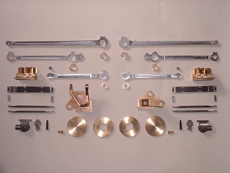
21/4/06 Kit 12 arrived at 8.00 this morning. It consists of the coupling and connecting rods and their bushes, the crossheads and slidebars, the motion brackets, the front and rear cylinder covers and dummy front pressure relief valves. The motion rods appear to be CNC machined rather than laser-cut, so relatively little finishing should be needed. The coupling rods are fish-bellied rather than fluted, which is correct for Oliver Cromwell, although the amount of fish-belly curvature looks to me somewhat less than it should be.
22/4/06 I did a trial assembly of the left-hand side motion. I fixed the front and rear coupling rods together and fitted them to the crankpins without any problems. I screwed the crosshead onto the end of the piston rod, and bolted the upper slidebar and slidebar bracket to the frames so that the slidebar just touched the top surface of the crosshead along the length of the piston travel. The three lower slidebar bracket Allen screws underneath the main stretcher were fiddly to fit. The lower slidebars were also difficult to fit - Ted had warned me about this. I eventually removed the upper slidebar and fitted the outer lower slidebar loosely by its front bolt before screwing the upper slidebar back to the slidebar bracket, since this bolt is immediately underneath the valve liner and cannot be inserted later. Fitting the nut to the inner front bolt is fiddly, but with patience can be done by holding it with cranked long-nosed pliers. Fortunately after all this the crosshead slid smoothly between the slidebars without any filing, although the instructions say some filing may be needed. With hindsight I should have checked the fit of the slidebars to the crosshead before starting the assembly. The connecting rod did need some filing to fit into the crosshead - the thickness of the little end needed reducing by about 0.2mm to fit into the slot in the crosshead, and then the top outer circumference of the little end needed filing slightly to allow the bearing holes to line up.
 23/4/06
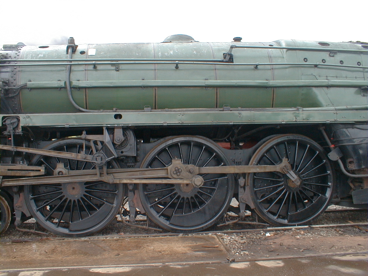
I spent this morning at the St Albans club track near King's Langley. There were four models in steam, including Tim's Modelworks 5" 57xx Pannier Tank Engine which was running nicely now that he has replaced the leaking automatic cylinder cocks with manual ones. Roger very kindly gave me a lesson on his 3.5" Princess Marina, my first experience of driving a model steam locomotive. He had stoked up the fire and water, so I just needed to work the regulator - very satisfying, although I can see that I've got a lot to learn. I then visited the North London SME track at Colney Heath, which is actually closer to my home - they have a very impressive track, but there were no steam locomotives running this afternoon. I'll try again another Sunday, because I gather that there is a 5" Britannia sometimes to be seen there. I started to clean up the coupling rods - this would not need much draw filing, except that I decided that the fish-belly curvature needed to be increased. The rear coupling rod as supplied is 11.1mm wide at the centre and 10.6mm at the ends, which makes the curvature hardly visible. By scaling from this photograph of 70000 I estimate that these measurements should be more like 12.6mm and 11.0mm. I therefore filed the ends of the rod down to give a width of 9.7mm, which is a bit of a compromise but does give a noticeable fish-belly effect. The photograph shows the before-and-after comparison.
23/4/06
I spent this morning at the St Albans club track near King's Langley. There were four models in steam, including Tim's Modelworks 5" 57xx Pannier Tank Engine which was running nicely now that he has replaced the leaking automatic cylinder cocks with manual ones. Roger very kindly gave me a lesson on his 3.5" Princess Marina, my first experience of driving a model steam locomotive. He had stoked up the fire and water, so I just needed to work the regulator - very satisfying, although I can see that I've got a lot to learn. I then visited the North London SME track at Colney Heath, which is actually closer to my home - they have a very impressive track, but there were no steam locomotives running this afternoon. I'll try again another Sunday, because I gather that there is a 5" Britannia sometimes to be seen there. I started to clean up the coupling rods - this would not need much draw filing, except that I decided that the fish-belly curvature needed to be increased. The rear coupling rod as supplied is 11.1mm wide at the centre and 10.6mm at the ends, which makes the curvature hardly visible. By scaling from this photograph of 70000 I estimate that these measurements should be more like 12.6mm and 11.0mm. I therefore filed the ends of the rod down to give a width of 9.7mm, which is a bit of a compromise but does give a noticeable fish-belly effect. The photograph shows the before-and-after comparison.
24/4/06 I finished polishing the left rear coupling rod and started on the left front one, filing the fish-belly to the same dimensions. It's difficult to polish the front boss because the front bearing has for some reason been glued in at the factory and the end of the bush projects slightly. I've emailed Debbie to check whether it's OK to heat the bearing to break the glue joint and remove it in order to polish the boss properly. I also intend to remove the oiling boxes from above the knuckle pins at the rear of the front coupling rods, since they are not present on the full-size locomotive as can be seen in the photograph of 70000 referenced above.
25/4/06 Debbie gave the go-ahead to remove the front bearing, so I did this by heating it over the gas ring and pushing the bearing out. I finished polishing the front left coupling rod and filed off the oilbox over the knuckle pin. I glued in the three left-hand bearings, taking care to line up the oil holes.
27/4/06 Back from another couple of days sailing - the weather is finally warming up. I joined the two left-hand coupling rods with the knuckle pin, having first cut a slot in the rear face of the pin using a cut-off wheel in the Dremel so that I could hold the pin while tightening the nut on the front. I've also now filed and polished the right rear coupling rod and started on the front one.
28/4/06 I finished polishing the right-hand coupling rods, fitted the knuckle pin and glued in the bearings. Unfortunately I can't yet check the coupling rods for free running because I'm still waiting to exchange the three sub-standard driving wheels from kit 8, and so I can't key the wheels to the axles and glue the axles and crankpins. Progress will be delayed if I don't get the replacements fairly soon.
29/4/06 I dismantled the trial assembly of the slidebars on the left-hand side, and started on the proper assembly on the right-hand side. The cylinder needs to be fixed permanently to the frames before the crosshead and slidebars can be adjusted, so I applied steam oil to the gasket and bolted the cylinder to the frames. I fitted the front and rear cylinder covers, with the dummy pressure relief valve on the front cover - the M3 bolts used to attach the covers were 6mm long and had to be cut down to the 4mm specified in the parts list. I started to polish up the crosshead and the slidebar components.
 30/4/06
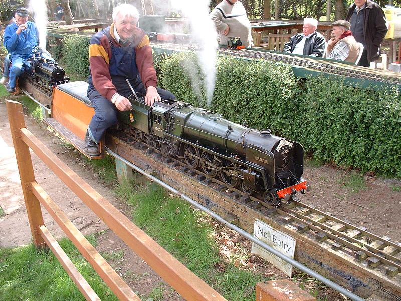
I visited the North London SME track again this afternoon and took this photo of Tony and his magnificent 5" Britannia, which he scratch-built to the Norman Spink plans. I finished polishing the right-hand crosshead, slidebars and slidebar bracket and fitted them together off the frames to check the movement - I needed to file a little off either end of the bearing face of the top slidebar to get a good uniform fit. I swapped over the crossheads so that the retaining grub screw is on the inside rather than the outside of the piston rod boss. This gives a neater appearance, and the grub screw is still accessible with an Allen key.
30/4/06
I visited the North London SME track again this afternoon and took this photo of Tony and his magnificent 5" Britannia, which he scratch-built to the Norman Spink plans. I finished polishing the right-hand crosshead, slidebars and slidebar bracket and fitted them together off the frames to check the movement - I needed to file a little off either end of the bearing face of the top slidebar to get a good uniform fit. I swapped over the crossheads so that the retaining grub screw is on the inside rather than the outside of the piston rod boss. This gives a neater appearance, and the grub screw is still accessible with an Allen key.
1/5/06 When fitting the top slidebar to line up with the crosshead I realised that the piston would not slide back fully - it jammed about 5mm short of its full travel. This was strange, since I had checked it before fixing the cylinder. I found that by rotating the piston rod half a turn it moved to the end quite freely, and this must have been the position in which I tested it. However, the crosshead needs to be screwed tight up to the shoulder on the piston rod and this forces a particular orientation for the rod. I can only assume that the piston is very slightly offcentre on the rod, and the boss in the rear cover needs to be aligned with this. So I removed the brass cover and slackened the screws in the cylinder cover slightly, then pulled the piston right back with the crosshead the right way up and retightened the screws. This cured the problem. I fitted the rest of the right-hand slidebar assembly, following the sequence described on 22/4 above.
 2/5/06
I filed and polished the right-hand connecting rod - the little end needed reducing in the same way as the left-hand rod. Fortunately the milled finish within the fluting was good enough to be finished with emery paper, because it would have been difficult to get a file to it. The motion does turn satisfactorily, as far as I can tell by rolling the chassis without glueing the wheels and crankpins, although it is fairly stiff - I need to get some advice on how free the motion should be before starting to run it in. Without the connecting rods, the wheels and coupling rods roll very freely and smoothly.
2/5/06
I filed and polished the right-hand connecting rod - the little end needed reducing in the same way as the left-hand rod. Fortunately the milled finish within the fluting was good enough to be finished with emery paper, because it would have been difficult to get a file to it. The motion does turn satisfactorily, as far as I can tell by rolling the chassis without glueing the wheels and crankpins, although it is fairly stiff - I need to get some advice on how free the motion should be before starting to run it in. Without the connecting rods, the wheels and coupling rods roll very freely and smoothly.
3/5/06 I polished the left-hand cylinder covers and fitted them. The rear cover needed quite a bit of scraping around the inside of the rim to get an easy fit - the other rear cover had also needed this. I think this is worth doing because the covers are bound to need removing at some stage, and it would make a mess of the paintwork if they had to be levered off with a screwdriver blade. I found that all the cylinder end plate screws could be tightened by a further 1/8th of a turn - the gaskets must have compressed since I originally fitted them. I then bolted the cylinder to the frames.
5/5/06 I spent yesterday on the annual chore of renewing the antifouling paint on the bottom of my boat - a backbreaking task. My wife always manages to organise a trip away during the week the boat is out of the water. Today I filed and polished the left-hand crosshead and slidebars and they are now ready for fitting. Ted tells me that he has finally received kit 15, which consists mainly of the ashpan and grate. It also contains replacements for the axlepump link and the brake crank to fix the problems that I discovered in kits 9 and 10 respectively.
8/5/06 I've now finished fitting the left-hand motion. This just leaves the weighshaft brackets to polish and fit, but I'll do these as part of kit 13 since this contains other parts to be fitted to them. I'll order kit 13 tomorrow.
| Next Kit | Previous Kit | Index |