29/4/08
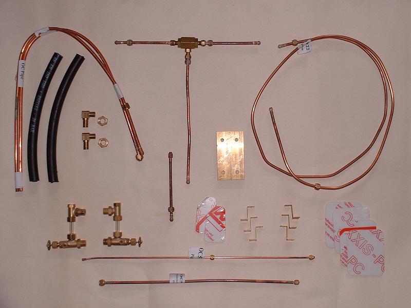
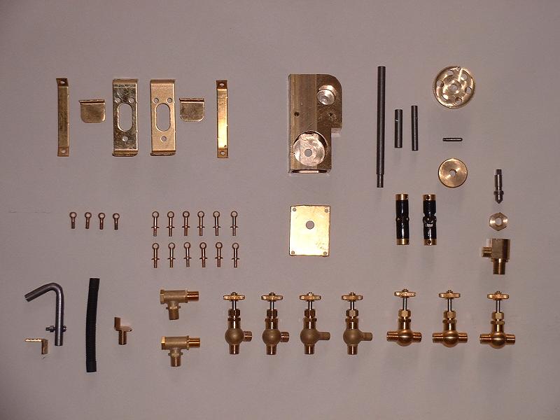
The 'final' kit finally arrived this morning, but disappointingly there are several parts listed as 'to follow', in addition to the injectors: the dome cover, the safety valves, the AWS battery box and the adaptor to connect the regulator valve to its operating spindle. The whistle valve is also listed, although we've already had one of these.The items included are as follows:
30/4/08 Dean called me again this afternoon to say that he'd been through my list below with Jim, and Jim will give him a set of dates tomorrow which Dean will let me have by Friday. I said that my priorities are the regulator adaptor and safety valves, so that I can get ready for a steam test. I've fitted the water gauge fittings into the backhead and they seem to line up nicely - I haven't tried fitting the glasses yet, but Ted tells me that his fit OK. The snifter pipes consist of three pipes joined by a T-piece which connect the fittings on the superheater outlet pipes to the snifter valve on the smokebox side. I haven't tried bending them to shape yet, but they look as though they will need shortening. I was slightly surprised at this arrangement because Ian T had told me that he'd recently received a modified banjo bolt for the superheater header with a pipe connection to run from there straight to the snifter valve, which sounds neater.
9/5/08 I hadn't heard from Dean, who is now at the Harrogate show, so I called Jim Rule to check on progress. He told me that the safety valves have been made and are being set to the correct pressure by Ian. He promised to send me mine when the first batch is ready next week. I know that a couple of builders have already had their safety valves, but this is because they asked for them unset. Jim also said that the regulator adaptor parts have been made but need to be checked on the control model before they are sent out. They consist of two short cranks, one hanging down from the valve spindle and the other pointing up from the smokebox spindle. He also said that the lost wax castings for the dome cover and the AWS battery box are still awaited from the supplier - the first batch of dome covers was unsatisfactory. The injectors will be made by Steamfittings. Jim is aware of the need for a new brake valve spindle, which I'd fabricated myself, but wasn't aware of the need for the working rear drawbar.
 11/5/08
I've fitted the water gauges into the backhead - they have adjustable nuts on the boiler fittings so that they can be tightened at the correct angle and can also be moved in and out to get the holes for the glass exactly in line - I used a 6mm rod to line them up while tightening the nuts down. I tried fitting the glasses, but they both seemed slightly too long and were nipped when tightening the top plugs down. I'll have to try shortening them slightly, which I suspect may be tricky, or perhaps I'll just buy a length of gauge glass with a red stripe and cut this to the correct length. I'll need some spare anyway. I fitted the drain pipes to the valves - the fittings point out to the sides to allow the pipes to be routed down on either side of the firebox door runners. Unfortunately the left-hand pipe clashed with my steam brake valve, so I'll have to make a new bracket for this and position it a little higher up and further out from the backhead. Photo to follow when I've done this.
11/5/08
I've fitted the water gauges into the backhead - they have adjustable nuts on the boiler fittings so that they can be tightened at the correct angle and can also be moved in and out to get the holes for the glass exactly in line - I used a 6mm rod to line them up while tightening the nuts down. I tried fitting the glasses, but they both seemed slightly too long and were nipped when tightening the top plugs down. I'll have to try shortening them slightly, which I suspect may be tricky, or perhaps I'll just buy a length of gauge glass with a red stripe and cut this to the correct length. I'll need some spare anyway. I fitted the drain pipes to the valves - the fittings point out to the sides to allow the pipes to be routed down on either side of the firebox door runners. Unfortunately the left-hand pipe clashed with my steam brake valve, so I'll have to make a new bracket for this and position it a little higher up and further out from the backhead. Photo to follow when I've done this.
14/5/08 I've made a new bracket for the steam brake valve and fitted the steam brake pipes. The top inlet pipe in my case runs from a T junction down the left hand side of the firebox, under the running board and up the backhead, which is different to the arrangement shown by Modelworks where it comes straight from the manifold. My arrangement is closer to the external pipework on 70013, although the unlagged vertical pipe in question is almost certainly not for the steam brake. The right-hand pipe from under the valve connects to the brake cylinder and the left-hand one is the exhaust.
 15/5/08
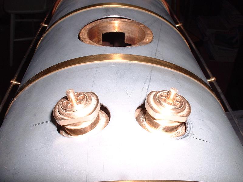
The safety valves arrived this morning as promised. The note with them said that they had been set at 90psi on compressed air and might need slight adjustment for steam. The bottom flanges are as large as the holes in the cladding and I had to open out both holes by about 1mm on the outer sides to align them and allow the safety valves to be screwed in. The stalks on the valves were over 10mm long and I trimmed them down to 5mm, which looks more realistic. I'm now just waiting for the regulator adaptor and then I'll be able to reassemble the superheaters and prepare for a steam test.
15/5/08
The safety valves arrived this morning as promised. The note with them said that they had been set at 90psi on compressed air and might need slight adjustment for steam. The bottom flanges are as large as the holes in the cladding and I had to open out both holes by about 1mm on the outer sides to align them and allow the safety valves to be screwed in. The stalks on the valves were over 10mm long and I trimmed them down to 5mm, which looks more realistic. I'm now just waiting for the regulator adaptor and then I'll be able to reassemble the superheaters and prepare for a steam test.
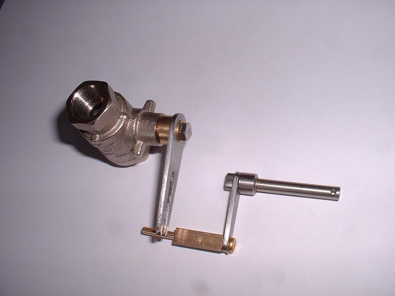
22/5/08 Just back from three days sailing - we went to Poole harbour and ventured all the way up the river Frome to Wareham, where we briefly ran aground. The regulator adaptor was waiting on the doormat when we got back, so I think that I now have everything I need to prepare for a steam test. The regulator adaptor consists of two cranks, one hanging down from the regulator valve with a slot to take a pin on the other shorter crank which hangs down from the operating spindle.
 24/5/08
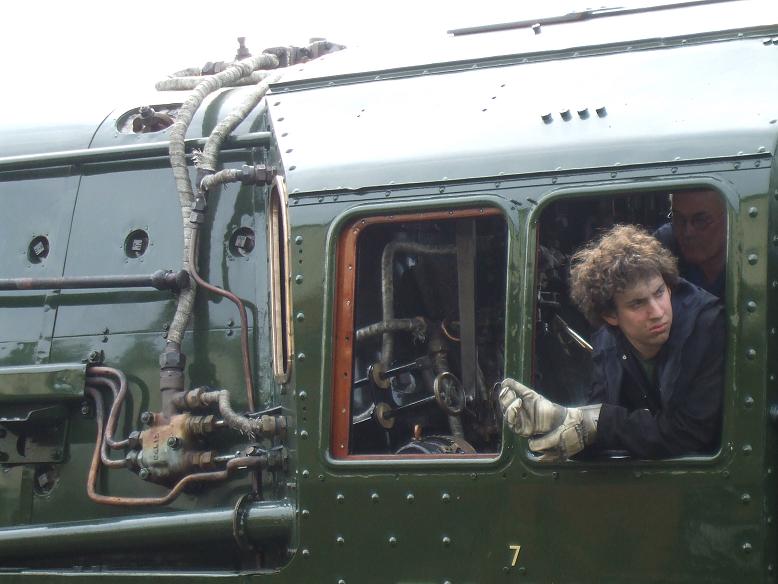
The photo shows the regulator adaptor cranks fitted to the valve and operating spindle. The instructions suggest shortening and hammering over the flat end of the spindle to retain the crank, but I'll silver solder mine. There's a fair amount of free play where the other crank fits over the flats on the valve spindle, so I'll probably silver solder the crank to the brass collar and then fit a taper pin through the collar and valve spindle. I've assembled the complete regulator linkage and it does just about work, but the valve is fairly stiff, particularly at the point where it closes, and this puts undue strain on the linkage - the rods along the side of the boiler are prone to flex out of line, one of them being in compression whether opening or closing the regulator. I'm a bit concerned that it may get even stiffer when the PTFE in the valve expands at working temperature. I might try making a slightly longer crank for the outside of the smokebox - this is only 8mm long and doesn't give much leverage. The red-lined gauge glass and spare injector union that I ordered from Polly arrived this morning. I see that Steamfittings are now advertising injectors, so it may be that these will be delivered via Modelworks before too long.
26/5/08
I've silver soldered the regulator adaptor cranks and experimented with a 12mm crank on the outside of the smokebox, which feels much better - it only opens the valve to about 60 degrees but this seems to be plenty of aperture when compared with the cross section of the superheater pipes, so I'll make a proper crank of this length. I've refitted the drain cock operating rod, which I'd left off some time ago - it's quite tricky to fit without being able to turn the loco upside down, and I had to bend the rod a bit and also open out the three guides under the horn stretchers in order to get it to operate reasonably freely and not foul the ashpan shutter spindle. I'm now starting to refit the boiler fittings and cladding prior to fitting the boiler and superheaters to the frames for a steam test.
24/5/08
The photo shows the regulator adaptor cranks fitted to the valve and operating spindle. The instructions suggest shortening and hammering over the flat end of the spindle to retain the crank, but I'll silver solder mine. There's a fair amount of free play where the other crank fits over the flats on the valve spindle, so I'll probably silver solder the crank to the brass collar and then fit a taper pin through the collar and valve spindle. I've assembled the complete regulator linkage and it does just about work, but the valve is fairly stiff, particularly at the point where it closes, and this puts undue strain on the linkage - the rods along the side of the boiler are prone to flex out of line, one of them being in compression whether opening or closing the regulator. I'm a bit concerned that it may get even stiffer when the PTFE in the valve expands at working temperature. I might try making a slightly longer crank for the outside of the smokebox - this is only 8mm long and doesn't give much leverage. The red-lined gauge glass and spare injector union that I ordered from Polly arrived this morning. I see that Steamfittings are now advertising injectors, so it may be that these will be delivered via Modelworks before too long.
26/5/08
I've silver soldered the regulator adaptor cranks and experimented with a 12mm crank on the outside of the smokebox, which feels much better - it only opens the valve to about 60 degrees but this seems to be plenty of aperture when compared with the cross section of the superheater pipes, so I'll make a proper crank of this length. I've refitted the drain cock operating rod, which I'd left off some time ago - it's quite tricky to fit without being able to turn the loco upside down, and I had to bend the rod a bit and also open out the three guides under the horn stretchers in order to get it to operate reasonably freely and not foul the ashpan shutter spindle. I'm now starting to refit the boiler fittings and cladding prior to fitting the boiler and superheaters to the frames for a steam test. I've reduced the head thickness of one of my blanking plugs and will fit this into the left-hand side of the firebox under the cladding to plug the superfluous blowdown valve hole.
28/5/08 I've fitted the boiler and superheaters and smokebox pipework as shown in this photo. I filed the upper edges of the steam pipe holes in the smokebox to allow the pipes to line up with the superheaters. These holes will need sealing later with some fire cement or similar to stop air leaks interfering with the draughting. It's quite a struggle to get the superheaters to fit, and I had to slacken the smokebox mounting bolts right off to manoeuvre them over the steam pipes. I discarded the long snifter pipe shown in the contents photo at the top of this page and fitted one end of the T-piece straight onto the snifter valve, behind the right hand steam pipe in this photo, and then ran the two short pipes from the T-piece to the fittings on the superheater pipes. I also fitted the blower pipe to its smokebox fitting behind the left hand steam pipe in the photo, and bent it to point up the chimney alongside the blastpipe. This was all extremely fiddly and it helped a great deal that I hadn't permanently pinned the smokebox door ring to the front of the smokebox. I hope that I don't have to remove the boiler again prior to steaming.
 30/5/08
I've had a couple of comments - which are always welcome - to the effect that my blower pipe probably won't work very well and should be replaced by a blower ring around the blastpipe nozzle, or at least should be secured lower down to the side of the nozzle. I'll investigate this further, but it shouldn't prevent a test steaming. I'm also told that silicone sealant will be OK for sealing the steam pipes. I've modified the blowdown valve on the right hand side of the firebox because it didn't have a shoulder long enough to seat onto the boiler bush through the thickness of the cladding, and it also looked rather too chunky. The original is shown at the right of the kit 16 contents photo. I cut off the threaded outlet pipe and reduced the body to a slightly thinner circular section using hacksaw, files and finally turning in the drill with files and then wet-and-dry paper - I really must get myself a lathe (although the result is parallel to within 0.02mm, so perhaps I don't really need one!). I then silver soldered on a new thinner outlet pipe at an angle so that the exhaust will not drench the injector, and adapted a smaller end nut from another superfluous fitting. The photo shows the result. The next job is to cut the red-lined gauge glass to length and fit the water gauges. I also need to find out how to dismantle the pressure gauge to mark a red line at 90psi - apparently this line must be on the dial rather than the covering glass.
30/5/08
I've had a couple of comments - which are always welcome - to the effect that my blower pipe probably won't work very well and should be replaced by a blower ring around the blastpipe nozzle, or at least should be secured lower down to the side of the nozzle. I'll investigate this further, but it shouldn't prevent a test steaming. I'm also told that silicone sealant will be OK for sealing the steam pipes. I've modified the blowdown valve on the right hand side of the firebox because it didn't have a shoulder long enough to seat onto the boiler bush through the thickness of the cladding, and it also looked rather too chunky. The original is shown at the right of the kit 16 contents photo. I cut off the threaded outlet pipe and reduced the body to a slightly thinner circular section using hacksaw, files and finally turning in the drill with files and then wet-and-dry paper - I really must get myself a lathe (although the result is parallel to within 0.02mm, so perhaps I don't really need one!). I then silver soldered on a new thinner outlet pipe at an angle so that the exhaust will not drench the injector, and adapted a smaller end nut from another superfluous fitting. The photo shows the result. The next job is to cut the red-lined gauge glass to length and fit the water gauges. I also need to find out how to dismantle the pressure gauge to mark a red line at 90psi - apparently this line must be on the dial rather than the covering glass.
1/6/08 I've managed to get the front off the pressure gauge - it is a press fit, held in place by two convex dimples on the sides of the rear cover. I carefully levered it forward with a very small screwdriver. It's important not to loosen the screws on the back, which hold the mechanism in place. I now just need to make a red line at the 90psi position - Julia tells me that she used a small screwdriver dipped in a puddle of paint, but I'll practice on some scrap before I risk trying this. In view of the sad demise of Modelworks, I've started to revise the list of issues below.
 3/6/08
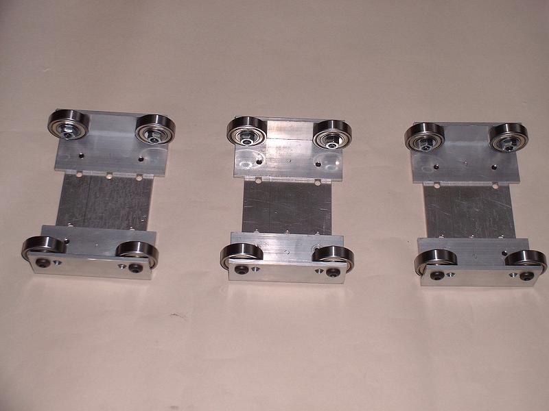
I've bought three driving wheel modules for a rolling road from Metalsmith, recommended to me by Ian T who used them for his testing on compressed air. These rest on top of the 5" track - they also make modules without rollers to support the bogie, pony and tender at the right height, but I'll buy some angle iron and fabricate the rest. The driver modules cost �30 each, so the complete assembly should cost significantly less than the �180 that Modelworks were charging. I've continued refitting the boiler fittings - I cut the red-lined water gauge glass that I bought from Polly to the correct length by filing a groove all the way round, wrapping it in a cloth and snapping it, and I have enough left over from the 6" length for two spares.
3/6/08
I've bought three driving wheel modules for a rolling road from Metalsmith, recommended to me by Ian T who used them for his testing on compressed air. These rest on top of the 5" track - they also make modules without rollers to support the bogie, pony and tender at the right height, but I'll buy some angle iron and fabricate the rest. The driver modules cost �30 each, so the complete assembly should cost significantly less than the �180 that Modelworks were charging. I've continued refitting the boiler fittings - I cut the red-lined water gauge glass that I bought from Polly to the correct length by filing a groove all the way round, wrapping it in a cloth and snapping it, and I have enough left over from the 6" length for two spares.
5/6/08 I've nearly finished refitting the boiler fittings and pipework. I've been using packs of copper shim washers of varying thicknesses to get the correct orientation and in some cases to clear the cladding. I plan to reposition the axlepump bypass valve so that it is more accessible in the cab - currently it is hidden behind the side bulkhead. I'll bring the pipe in nearer the centre of the cab. I've updated the information below with dimensions of the regulator adaptor for those wishing to fabricate their own. I've bought a 6" square of brass gauze from Blackgates to make better water filters, but they don't have flexible hose suitable for 3/16" pipe - they say that 5mm is too loose and 4mm too tight, so I'll need to look elsewhere for 4.5mm. I also ordered a 5" Britannia gunmetal outer dome casting which they have in their catalogue, but they are awaiting a new batch from the foundry so it will be 2-3 weeks before I get this.
 10/6/08
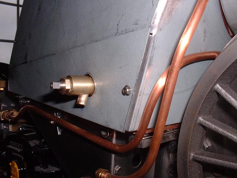
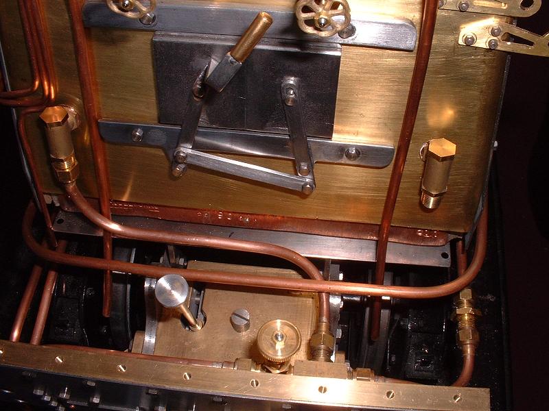
I've repositioned the axlepump bypass valve as shown in the photo - the valve will be much easier to operate in this position and I was able to reuse the existing fittings. The return pipe to the tender is now on the left hand side. I'll order the 'luxury' 3/4" handwheels from Steamfittings to match the smaller ones on the water gauges at the top of the photo - they are not strictly the correct Gresham and Craven style for BR Standards, but should be easy to handle. I've bought some steel from B&Q to fabricate the rest of the rolling road - two 2m lengths of 25x25x3mm angle for the lower rails, two 2m lengths of 25mmx4mm bar for the upper rails and buffers, a 1m length of M10 studding for the cross pieces, and M6 nuts and bolts.
10/6/08
I've repositioned the axlepump bypass valve as shown in the photo - the valve will be much easier to operate in this position and I was able to reuse the existing fittings. The return pipe to the tender is now on the left hand side. I'll order the 'luxury' 3/4" handwheels from Steamfittings to match the smaller ones on the water gauges at the top of the photo - they are not strictly the correct Gresham and Craven style for BR Standards, but should be easy to handle. I've bought some steel from B&Q to fabricate the rest of the rolling road - two 2m lengths of 25x25x3mm angle for the lower rails, two 2m lengths of 25mmx4mm bar for the upper rails and buffers, a 1m length of M10 studding for the cross pieces, and M6 nuts and bolts.
11/6/08 I've fitted the whistle and pipework. I decided to mount the whistle under the running board on top of the right hand cylinder, where it is less obtrusive than behind the smoke deflector. I fitted a bracket to the front cladding fixing hole on the top of the cylinder with a 6BA bolt and bolted the front of the whistle to this bracket. The pipe runs down the side of the firebox inside the cab and then forward under the running board. The pipe is a bit too long, and would be even with the whistle in the standard position. I've ordered a hydraulic lifting trolley from Machine Mart to move the locomotive around.
13/6/08 I've now completed fitting all the locomotive pipework, including a separate handpump feed to the right hand clack on the backhead, and I've red-lined the pressure gauge at 90psi using a pinstriping decal from the local model aeroplane shop, having chickened out of trying to paint a neat red line. I decided to try a pressure test to check whether all the fittings were steamtight, so I connected up my compressor to the handpump inlet clack and set it to 10psi. The pressure gauge rose to 10psi, but there was quite a lot of leakage around the various connections on the manifold, including the manifold to boiler connection. I brushed soapy water over all the fittings to locate the leaks - all the other fittings seemed OK. The blower valve produced a reasonable blast up the chimney, the whistle made a strange strangled noise, and the injector valves produced a rush of air. The brake valve had no detectable effect, but no doubt needs more pressure to move the piston. I cautiously opened the regulator with the motion in mid gear, and there was a rush of air to the blastpipe - presumably the same problem of leakage past the right hand piston valve that I detected two years ago. If this doesn't improve with running in (a faint hope, I fear) I'll need to replace the piston valves. I'll now try to sort out the leaking manifold and repeat the test to a higher pressure, not least to try to get a proper toot out of the whistle.
14/6/08 The leakage on the manifold fittings seems to be caused by the fact that the threaded holes for the pipe nipples and blanking plugs along the front and rear faces are quite shallow where they cut into the hole running through from side to side - there are only 2 or 3 turns of thread on the centreline, although more at the top and bottom. This coupled with the fact that the fittings have an undercut between the thread and the hexagonal shoulder means that it is difficult to get a good seal with PTFE tape, so I'm thinking of running some soft solder into the threads to seal them properly. I did get a sufficiently good seal with PTFE to raise the pressure to 50psi with my compressor, and at this pressure the whistle gave a reasonable note and the steam brakes worked surprisingly well - the chassis can be rolled along with one finger with the brakes off, but is hard to move with them on.
17/6/08 I've soft soldered the manifold fittings and this has cured the leaks there, although I've now noticed that both of the globe valves for the injector steam feeds leak slightly when closed - I'll have to see whether this causes problems when running, and if so try to get Steamfittings to replace them. The hydraulic lifting trolley arrived today and looks ideal for moving the locomotive around - I'll soon need to get it from my study to the garage for the initial steam test on the rolling road. I still haven't found the correct diameter flexible hose for the tender pipe connections, although I'm told that washing machine spare part shops may have it. I've discovered that the flexible hose and clamps supplied in kit 18a will be OK for the pressure connection to the tender handpump - the hose is 11mm outside and 5mm inside diameter, but the clamps hold it securely on the 3/16" pipe. I'll attach a stub of copper pipe to the locomotive end of the hose so that it can be connected quickly to a union on the end of the pipe leading to the clack valve. The additional hoses supplied in kit 18c are even bigger and are clearly the wrong size.
19/6/08 I've bought some 3/16" internal diameter black rubber hose from Maidstone Engineering. This looks good but is a fairly easy sliding fit on the pipes - to avoid searching any further I'll solder a collar cut from a pipe nipple to the end of each pipe to give a firmer push fit and to ensure that air cannot be sucked in, which is fatal for injectors. I've refitted the cab, which is quite tricky with all my modified pipework - I had to cut a slit from the front of the cab floor back to the position of my relocated axlepump bypass valve, but this is not a problem since I'm going to cover it with a false floor of wood and chequerplate. There are in any case other superfluous holes in the floor, and I think that the one for the tender drawbar pin will need to be repositioned. This completes the work on the locomotive prior to steam testing - I now just need to finish the tender pipework and filters, and build my rolling road.
 26/6/08
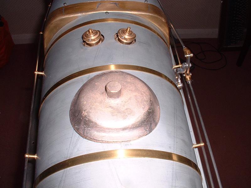
I had no reply from the subcontractor who was making the lost wax cast dome covers and AWS boxes, so I've bought a 5" Britannia gunmetal dome cover casting from Blackgates. This cost �13.09 including P&P. It fits snugly over the inner dome screws and exactly matches the curve of the cladding. The casting sprue obviously needs removing and the flange needs thinning and trimming, but it should look good when it's polished up. I'll fix it with 6 10BA bolts tapped into the cladding, rather than a central countersunk screw into the inner dome cover which I think Modelworks had intended.
26/6/08
I had no reply from the subcontractor who was making the lost wax cast dome covers and AWS boxes, so I've bought a 5" Britannia gunmetal dome cover casting from Blackgates. This cost �13.09 including P&P. It fits snugly over the inner dome screws and exactly matches the curve of the cladding. The casting sprue obviously needs removing and the flange needs thinning and trimming, but it should look good when it's polished up. I'll fix it with 6 10BA bolts tapped into the cladding, rather than a central countersunk screw into the inner dome cover which I think Modelworks had intended.
8/7/08 Richard P pointed out, just as I was about to cut it off, that the protrusion on the dome casting is a spigot for turning it in a lathe, rather than a casting sprue. However, it would only be possible to turn some parts of the surface, and it already looks pretty clean and true, so I've decided to go ahead and cut the spigot off and file and polish the casting by hand. I've started building the rolling road, which I'll hopefully have finished by tomorrow.
 9/7/08
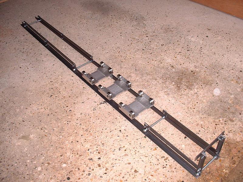
I've completed the rolling road, using the components from Metalsmith and B&Q listed on 3/6/08 and 10/6/08 above respectively. The lower angle strips are joined by lengths of M10 studding to give the correct separation, and the upper rails are set 35mm above the lower rails to raise the bogie, pony and tender wheels to the same height as the driving wheels resting in the roller units. There's a buffer beam at the front aligned with the loco buffers. It all seems pretty rigid. I now just need to make a few final checks on the loco, get some coal and a shovel and line up some suitably experienced helpers and I'll be ready for the first steam test in my garage, hopefully sometime next week!
9/7/08
I've completed the rolling road, using the components from Metalsmith and B&Q listed on 3/6/08 and 10/6/08 above respectively. The lower angle strips are joined by lengths of M10 studding to give the correct separation, and the upper rails are set 35mm above the lower rails to raise the bogie, pony and tender wheels to the same height as the driving wheels resting in the roller units. There's a buffer beam at the front aligned with the loco buffers. It all seems pretty rigid. I now just need to make a few final checks on the loco, get some coal and a shovel and line up some suitably experienced helpers and I'll be ready for the first steam test in my garage, hopefully sometime next week!
13/7/08 I've filed and polished the dome cover, and it looks very good. The rubber hoses between loco and tender fit nicely, with collars cut from pipe nipples soldered near the ends of the pipes to provide extra grip. I've ordered a shovel and poker from Polly. The coupling between loco and tender is a bit problematic - it looks as though the intention was for the tender pin to be withdrawn up through the hole near the rear of the cab floor to uncouple, but in fact this pin is right underneath the angle across the rear of the cab, so I can't drill a hole here to withdraw the pin. I'll therefore have to use the front pin in the loco drag box. This is under the cab floor but there is enough clearance to lift it far enough to release the drawbar without making yet another hole in the cab floor. I plan to solder a thin rod into the side of the head of this pin, projecting far enough out under the left side of the cab to allow it to be lifted up easily. I'll then make some sort of spring retaining clip to hook over this rod so that it can't accidentally rise up and release the coupling when driving. All being well I'm planning to have my first test steam on Wednesday - I've got Ted and Derek lined up to help. Ted is also very nearly ready to steam his Britannia.
Details of the steam trials can be found here.
Issues outstanding following the demise of Modelworks
Modelworks was placed into administration on 30/5/08 and it seems to me unlikely that we will see any further deliveries from them at least on the locomotive side, although it's always possible that the business will be sold as a going concern. In view of this I've listed outstanding issues and missing parts. I'll try to locate alternate suppliers wherever possible and list them here. Where I've already described a work-around for a faulty or missing part elsewhere in the text, I've removed it from this list.
| Previous Kit | Index |