 20/3/06
I ordered kit 10 this morning.
20/3/06
I ordered kit 10 this morning.
20/3/06
I ordered kit 10 this morning.
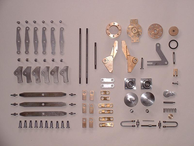
21/3/06 Kit 10 arrived at 8.00 this morning. It consists of the locomotive brakes, the brake linkage, and the steam-operated brake cylinder, along with the front buffers, drawhook and coupling links. It's a fairly small kit, but it's nice to see a proper steam brake included. I loosely assembled the brake cylinder and bolted it to the rear stretcher. The crank arm linking the piston rod to the brake pullrods has been drilled 6mm instead of 5mm for its pivot pin, so I've alerted Debbie.
22/3/06 I assembled the brake cylinder properly with the O-ring on the piston and found that it was a very tight fit in the bore - it would stick and then couldn't be moved by hand, even though I'd oiled the O-ring as per the instructions. This probably wouldn't prevent the brakes being applied, since 90lb/sq" of steam pressure on a piston area of just over 3/4 sq" will give a thrust of nearly 70lb, but I was concerned that the brakes would not release when the steam valve was closed. I dismantled it and inspected the cylinder bore and found a lot of tiny concentric ridges left by the boring tool. I polished these out by hand using first 400 grade and then 1200 grade wet and dry paper to give a mirror finish. This cured the problem - the piston now moves smoothly under hand pressure, although it's certainly still a firm enough fit to give a good seal.
 23/3/06
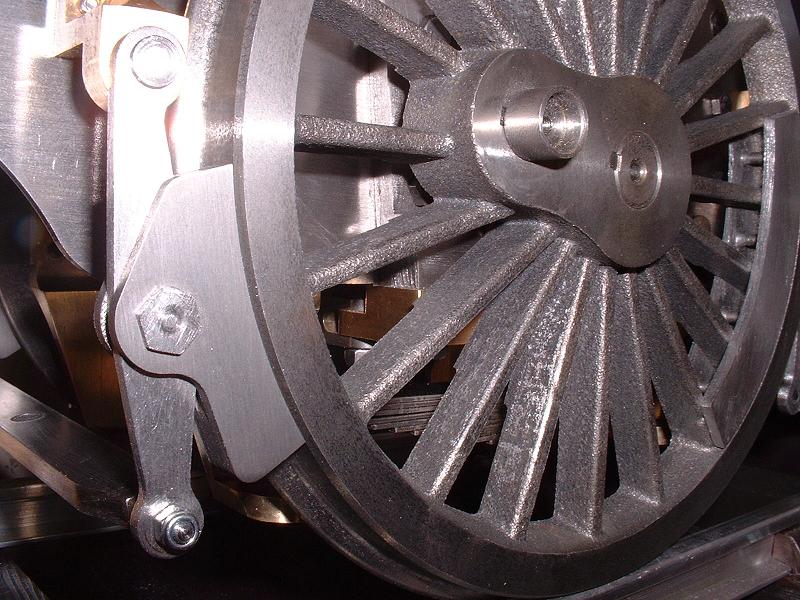
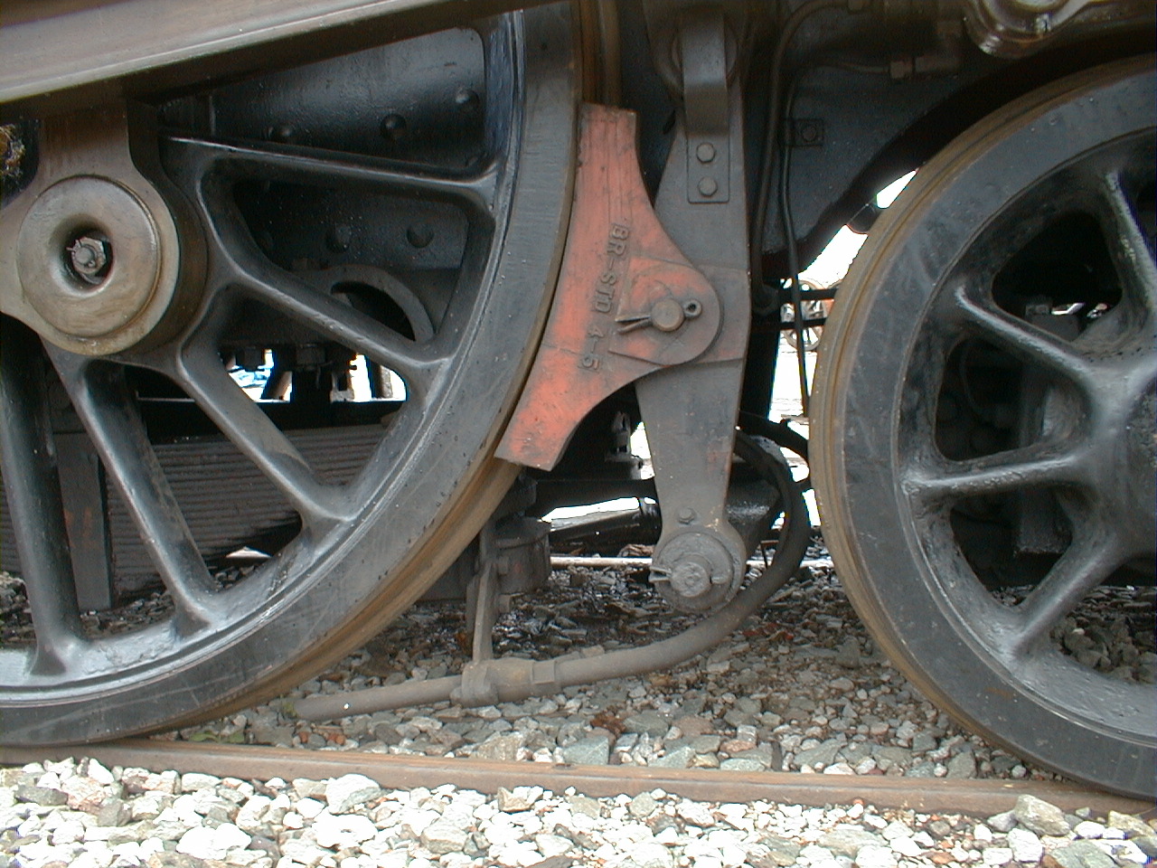
I started to clean up and fit the brake hangers and shoes. I fitted the top pins with their split pins on the inside rather than the outside, which I think looks more realistic. The brake shoes are the wrong shape - the real ones have a simple symmetrical shape as show here. This is rather odd, since the tender brake shoes hidden behind the frames are the correct shape, although of course they can't be interchanged since the wheel radius is different. I've noticed that some scratch-built Britannias show a similar error - I guess the error originated in some drawings that everyone has worked from. If I had a milling machine I could improve the shape, but it would be difficult to do a good job with hand tools so I shall leave them as they are.
23/3/06
I started to clean up and fit the brake hangers and shoes. I fitted the top pins with their split pins on the inside rather than the outside, which I think looks more realistic. The brake shoes are the wrong shape - the real ones have a simple symmetrical shape as show here. This is rather odd, since the tender brake shoes hidden behind the frames are the correct shape, although of course they can't be interchanged since the wheel radius is different. I've noticed that some scratch-built Britannias show a similar error - I guess the error originated in some drawings that everyone has worked from. If I had a milling machine I could improve the shape, but it would be difficult to do a good job with hand tools so I shall leave them as they are.
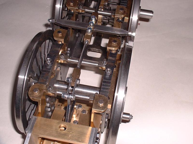
24/3/06 I fitted the rest of the brake hangers and shoes, and started to assemble the brake stretchers that connect the lower ends of the brake hangers on opposite sides, and the pullrods that connect the stretchers along their centre line. As with the pullrods on the tender, the linkage is rather floppy and can be improved by clamping the pullrod end fittings tightly between the connecting plates, still leaving the stretchers free to pivot and so equalise the pressure on each side. This can be achieved either by placing an M6 washer under the head of each link pin, or by cutting back the shoulders on the link pins so that the nuts can be tightened further. Tomorrow I'm planning to visit the Great Central Railway at Loughborough - they have an open day, and I should be able to see Oliver Cromwell in the workshops.
 25/3/06
I've just returned from an excellent day at the GCR where I saw Oliver Cromwell being rebuilt in the workshops and took some photographs. I also had a 16 mile round trip to Leicester on the footplate of a class 47 diesel locomotive at the invitation of Nigel, a volunteer at the GCR who has been following my website. I met up with Harry L who had seen my entry yesterday and decided to come along too to see Oliver Cromwell. In fact it seems that the workshops are open to the public every day for the cost of a platform ticket, so I shall try to go along every month or so to follow the progress of the rebuild, and perhaps even volunteer to help.
25/3/06
I've just returned from an excellent day at the GCR where I saw Oliver Cromwell being rebuilt in the workshops and took some photographs. I also had a 16 mile round trip to Leicester on the footplate of a class 47 diesel locomotive at the invitation of Nigel, a volunteer at the GCR who has been following my website. I met up with Harry L who had seen my entry yesterday and decided to come along too to see Oliver Cromwell. In fact it seems that the workshops are open to the public every day for the cost of a platform ticket, so I shall try to go along every month or so to follow the progress of the rebuild, and perhaps even volunteer to help.
27/3/06 I fitted the brake stretchers and pullrods. The pullrods were slightly too long - the instructions do say that they may need to be shortened slightly - so I removed a couple of millimetres from the ends and with the locknuts at the inner limit of the threads they now just allow the brakes to pull reasonably evenly on the three axles. The grip on the central axle is a bit less than on the other two - it's not possible to get an exact balance because half a turn of the pullrod ends is too big an adjustment but, as the instructions say, the cast iron brake blocks will no doubt bed in after some use. This completes the braking system, apart from sorting out the oversized pivot hole in the crank arm when I hear back from Modelworks - I'm not sure if it's a general fault or a one-off error on my kit.
 28/3/06
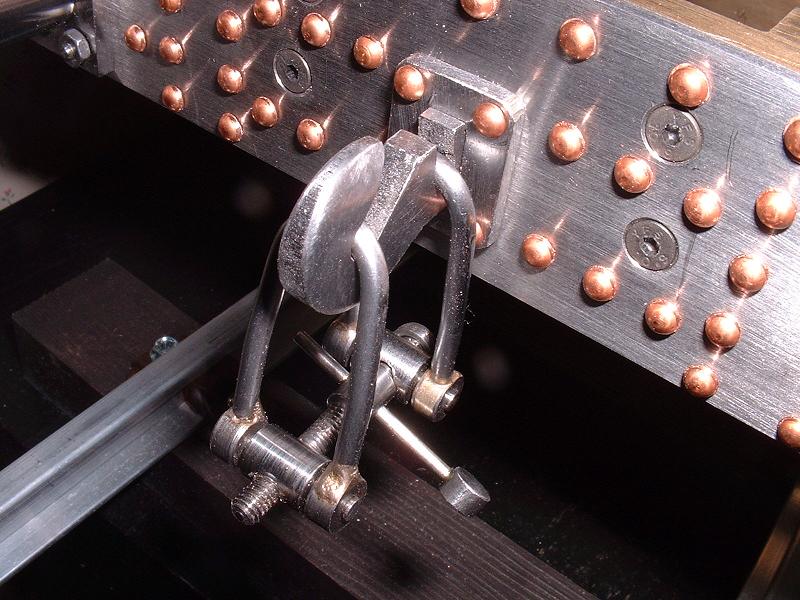
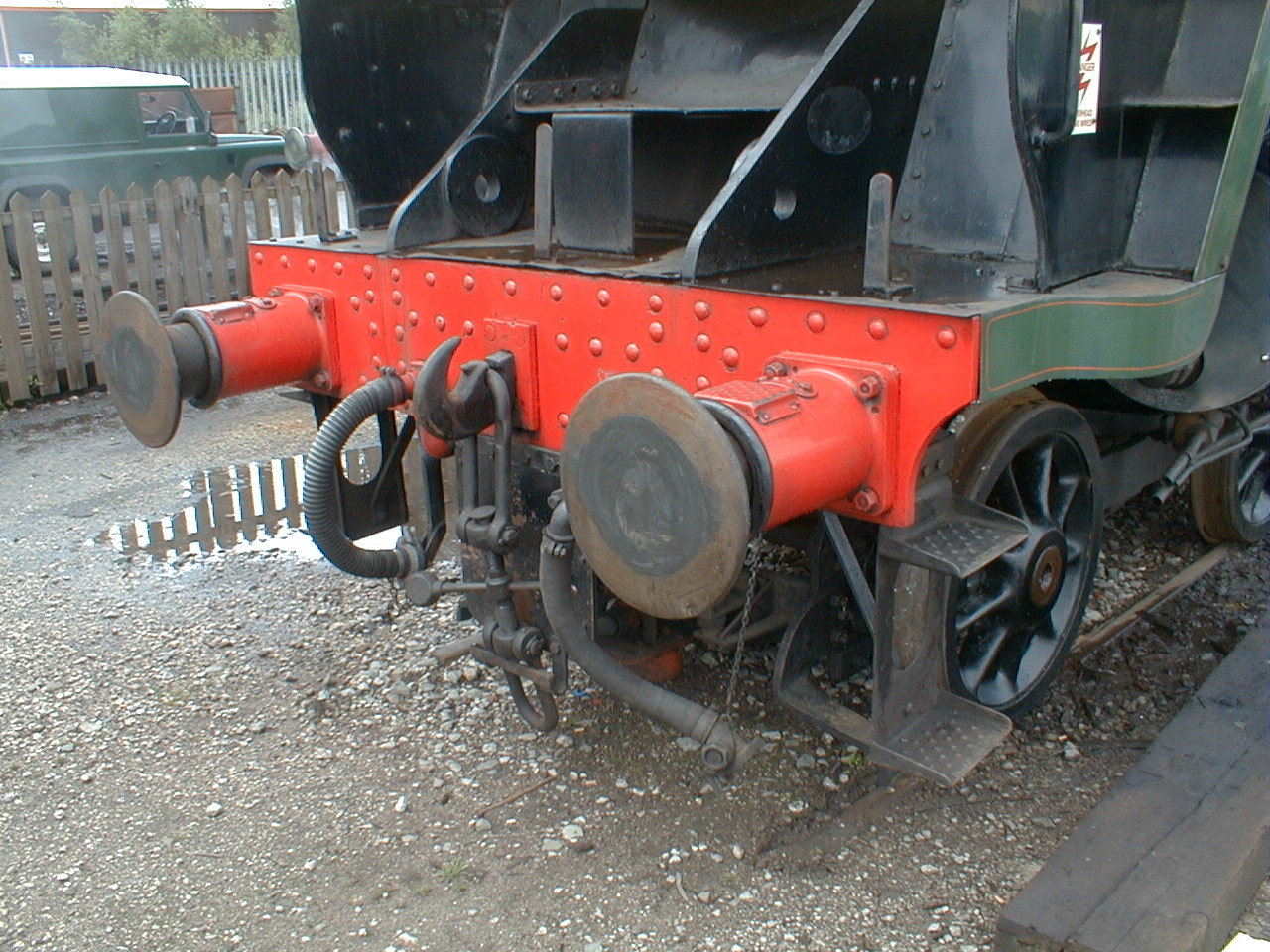
I polished the buffer heads to a mirror finish and fitted the buffers, using M3 studs and nuts in place of the bolts supplied, as in full-size practice. I filed the drawhook to a point and fitted it - the slot in the buffer beam was too big top-to-bottom, so I glued thin strips of brass to the top and bottom of the drawhook to stop it tilting in the slot. I made up the coupling links - I fitted a 6mm steel disk with a 2mm hole in one side to one end of the crossbar, and ground the nut on the short end of the threaded rod down to a smooth collar. This completes kit 10, apart from the brake crank arm - Debbie has just told me that a new batch of these will be made, which will take a couple of weeks as they have to be laser-cut. I shall do some more painting over the next few days and then order kit 11, the cylinders and pistons, early next week. Update 21/6/06: a new crank with a brass bearing was delivered in kit 15.
28/3/06
I polished the buffer heads to a mirror finish and fitted the buffers, using M3 studs and nuts in place of the bolts supplied, as in full-size practice. I filed the drawhook to a point and fitted it - the slot in the buffer beam was too big top-to-bottom, so I glued thin strips of brass to the top and bottom of the drawhook to stop it tilting in the slot. I made up the coupling links - I fitted a 6mm steel disk with a 2mm hole in one side to one end of the crossbar, and ground the nut on the short end of the threaded rod down to a smooth collar. This completes kit 10, apart from the brake crank arm - Debbie has just told me that a new batch of these will be made, which will take a couple of weeks as they have to be laser-cut. I shall do some more painting over the next few days and then order kit 11, the cylinders and pistons, early next week. Update 21/6/06: a new crank with a brass bearing was delivered in kit 15.
29/3/06 I filled some blemishes in the bogie and pony parts - mainly countersunk screw heads that hadn't been filled completely - then rubbed everything down with 1200 grade wet-and-dry paper and wiped it with the 'tack cloth' (a sticky cloth designed to remove dust which I bought from Phoenix, although I've since noticed that Halfords sell them too). I then had a big airbrushing session, coating all the parts three times in the space of an hour or so. I'm now getting a high gloss finish which I'm very pleased with. Opening up the airbrush flow control to give a wider spray pattern has made a big improvement, and I'm using about two parts enamel to one of quick-drying thinners, air pressure of about 25-30 lb/sq", and holding the airbrush about 2-3 inches from the work. With this set-up, I think a primed surface could be completely painted with three or four coats in a single session.
30/3/06 There were a few remaining blemishes and dust marks on the paintwork, so I rubbed down the most conspicuous parts - the bogie wheels and equaliser bars and the outside faces of the pony truck - with 1200 grade wet-and-dry. I shall need to take more care to prevent dust getting onto the surface for the final coat.
1/4/06 I've just purchased four buffer step castings from Doug Hewson, along with two pieces of dimpled plate for the steps on the top rear of the tender. The buffer steps are more realistic than the machined brass ones in the kit, and only cost Ł12 for four. I'll put what will hopefully be the final coat of paint on the bogie and pony tomorrow.
3/4/06 I had another airbrushing session yesterday and the bogie and pony are nearly there, although the outer edges of the wheel faces did not have a very clean edge when I removed the masking tape. It may be easier to paint the small bevel on the wheel rims than to mask it off. I'll have to sort this out when I next have a painting session. We went down to the boat today and had our first sail of the season, across to Newtown Creek on the Isle of Wight. I've ordered kit 11, the cylinders and pistons.
| Next Kit | Previous Kit | Index |